Table of Contents 
DESCRIPTION 
Connect an ESP8266 to a Raspberry Pi:
-
flash the ESP8266 using the Raspberry Pi serial interface
-
reset the ESP8266 by toggling GPIO5 on the Raspberry Pi from HIGH/LOW/HIGH
-
put the ESP8266 into programming mode for flashing by toggling GPIO6 on the Raspberry Pi from HIGH/LOW/HIGH
-
interact with the ESP8266 from the Raspberry Pi using AT commands over the serial interface
See:
-
https://www.instructables.com/Flash-ESP-01-ESP8266-Without-USB-to-serial-Adapter/
-
https://blog.3d-logic.com/2017/12/01/using-raspberry-pi-to-flash-esp8266/
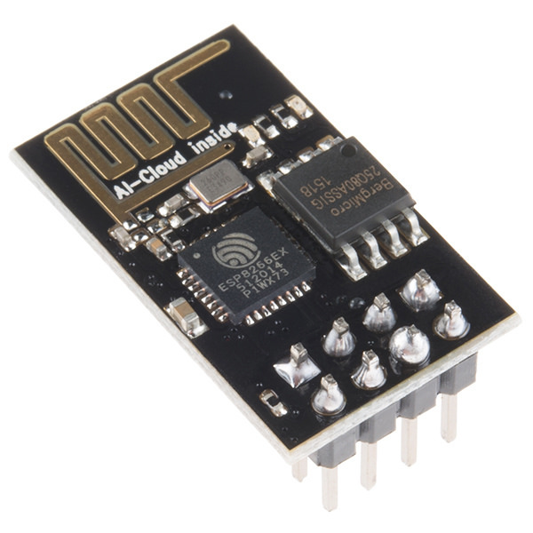
ESP8266 PINOUT 
Note the pin out assumes that:
-
the pins are facing away
-
the antenna to the right
| LEFT | RIGHT | ANTENNA |
|---|---|---|
| TX | GND | |
| CH_PD | GPIO2 | |
| RST | GPIO0 | |
| VCC | RX |
| PIN | DESCRIPTION |
|---|---|
| TX | Serial transmit |
| CH_PD | Chip power down or chip enable |
| RST | Reset: force ESP8266 to reboot |
| VCC | 3.3V power |
| GND | Ground |
| GPIO2 | Available GPIO |
| GPIO0 | Used for entering flash mode |
| RX | Serial receive |
RASPBERRY PI PINOUT 
        Rev 2 and 3 Raspberry Pi                        Rev 1 Raspberry Pi (legacy)
+-----+---------+----------+---------+-----+      +-----+--------+----------+--------+-----+                                                                             | BCM |   Name  | Physical | Name    | BCM |      | BCM | Name   | Physical | Name   | BCM |
+-----+---------+----++----+---------+-----+      +-----+--------+----++----+--------+-----+                                                                             |     |    3.3v |  1 || 2  | 5v      |     |      |     | 3.3v   |  1 ||  2 | 5v     |     |
|   2 |   SDA 1 |  3 || 4  | 5v      |     |      |   0 | SDA    |  3 ||  4 | 5v     |     |                                                                             |   3 |   SCL 1 |  5 || 6  | 0v      |     |      |   1 | SCL    |  5 ||  6 | 0v     |     |
|   4 | GPIO  7 |  7 || 8  | TxD     | 14  |      |   4 | GPIO 7 |  7 ||  8 | TxD    |  14 |                                                                             |     |      0v |  9 || 10 | RxD     | 15  |      |     | 0v     |  9 || 10 | RxD    |  15 |
|  17 | GPIO  0 | 11 || 12 | GPIO  1 | 18  |      |  17 | GPIO 0 | 11 || 12 | GPIO 1 |  18 |                                                                             |  27 | GPIO  2 | 13 || 14 | 0v      |     |      |  21 | GPIO 2 | 13 || 14 | 0v     |     |
|  22 | GPIO  3 | 15 || 16 | GPIO  4 | 23  |      |  22 | GPIO 3 | 15 || 16 | GPIO 4 |  23 |                                                                             |     |    3.3v | 17 || 18 | GPIO  5 | 24  |      |     | 3.3v   | 17 || 18 | GPIO 5 |  24 |
|  10 |    MOSI | 19 || 20 | 0v      |     |      |  10 | MOSI   | 19 || 20 | 0v     |     |                                                                             |   9 |    MISO | 21 || 22 | GPIO  6 | 25  |      |   9 | MISO   | 21 || 22 | GPIO 6 |  25 |
|  11 |    SCLK | 23 || 24 | CE0     | 8   |      |  11 | SCLK   | 23 || 24 | CE0    |   8 |                                                                             |     |      0v | 25 || 26 | CE1     | 7   |      |     | 0v     | 25 || 26 | CE1    |   7 |
|   0 |   SDA 0 | 27 || 28 | SCL 0   | 1   |      +-----+--------+----++----+--------+-----+                                                                             |   5 | GPIO 21 | 29 || 30 | 0v      |     |
|   6 | GPIO 22 | 31 || 32 | GPIO 26 | 12  |                                                                                                                             |  13 | GPIO 23 | 33 || 34 | 0v      |     |
|  19 | GPIO 24 | 35 || 36 | GPIO 27 | 16  |                                                                                                                             |  26 | GPIO 25 | 37 || 38 | GPIO 28 | 20  |
|     |      0v | 39 || 40 | GPIO 29 | 21  |                                                                                                                             +-----+---------+----++----+---------+-----+
CONNECTING ESP8266 TO RASPBERRY PI 
-
ESP8266: RST and GPIO0 should be set to HIGH (3.3V) for the ESP8266 to boot
-
Raspberry Pi: GPIOs up to 8 are default set to HIGH
-
ESP8266: VCC and CH_PD connected to a 3.3V pin on the RPI using a 10K resistor
| ESP8266 | RPI | ESP8266 | RPI | NOTES |
|---|---|---|---|---|
| TX | RxD (10) | GND | GND (14) | Use any available GND (0v) on RPI |
| CH_PD | 3.3V (17) | GPIO2 | unused | CH_PD attached via a 10K resistor |
| RST | GPIO21 (29) | GPIO0 | GPIO22 (31) | Use any available GPIO8 or lower |
| VCC | 3.3V (17) | RX | TxD (14) | VCC and CH_PD to 3.3V via a 10K resistor |
CODE 
List Available GPIO PINS 
Compile and run:
GOARCH=arm go build -o gpiolist main.go
gpiolist
package main

import (
	"fmt"
	"log"

	"periph.io/x/conn/v3/gpio/gpioreg"
	"periph.io/x/host/v3"
)

func main() {
	if _, err := host.Init(); err != nil {
		log.Fatalln(err)
	}

	for _, p := range gpioreg.All() {
		fmt.Printf("%s %s\n", p, p.Function())
	}
}
Set GPIO Pin State 
Compile and run:
GOARCH=arm go build -o gpioset main.go
gpioset 10 high
package main

import (
	"log"
	"os"
	"strconv"

	"periph.io/x/conn/v3/gpio"
	"periph.io/x/conn/v3/gpio/gpioreg"
	"periph.io/x/host/v3"
)

func main() {
	if len(os.Args) != 3 {
		log.Fatalf("usage: %s: <PIN> <PINSTATE>", os.Args[0])
	}

	n, err := strconv.Atoi(os.Args[1])
	if err != nil {
		log.Fatalln(err)
	}

	output := os.Args[2]

	if _, err := host.Init(); err != nil {
		log.Fatalln(err)
	}

	pin := gpioreg.ByName(strconv.Itoa(n))

	switch output {
	case "high", "on":
		err = pin.Out(gpio.High)
	case "low", "off":
		err = pin.Out(gpio.Low)
	}

	if err != nil {
		log.Fatalln(err)
	}
}
Flash 
# clone the image
git clone https://github.com/espressif/ESP8266_NONOS_SDK
cd ESP8266_NONOS_SDK/bin

# set the ESP8266 to flash mode
gpioset 6 low

# poweroff the ESP8266
gpioset 5 low

# flash the image
esptool --port /dev/serial0 --baud 115200  write_flash --flash_freq 40m --flash_mode qio 0x0000 boot_v1.7.bin 0x1000 at/512+512/user1.1024.new.2.bin 0x7E000 blank.bin

# in another shell: poweron the ESP8266
gpioset 5 high

#### when flashing is complete

# disable flash mode
gpioset 6 high

gpioset 5 low
gpioset 5 high
(markdown)